
Tiled per-triangle soft shadow volumes
In this post, I want to share a technique for rendering variable penumbra soft shadows in real time by using per-triangle shadow volumes. For each fragment, shadow casting triangles are software-rasterized in shader to determine light occlusion. Culling shadow volumes is done per 16×16 screen tile (similar to “tiled deferred shading”) and uses the mesh clusters of the existing GPU-driven renderer. The resulting shadows are alias-free, work correctly with multiple casters at different distances, and even exhibit interesting real-world artifacts. While I think this is very interesting and promising, it’s still nowhere near production-ready for most games.
🔑 Key takeaways
- Produces realistic soft shadows with variable penumbra
- Tile-based culling similar to tiled deferred rendering
- 60 FPS at 4k with 13M triangles in scene (on RTX 4070), but varies a lot depending on multiple factors
- Textured geometry (alpha masking) possible in theory, likely infeasible in practice
Context: I came up with this during the past few months of experimenting with shadow volumes. All images/videos are from my graphics playground which will hopefully grow to become a game at some point. No engine is used and everything is built on top of wgpu directly.
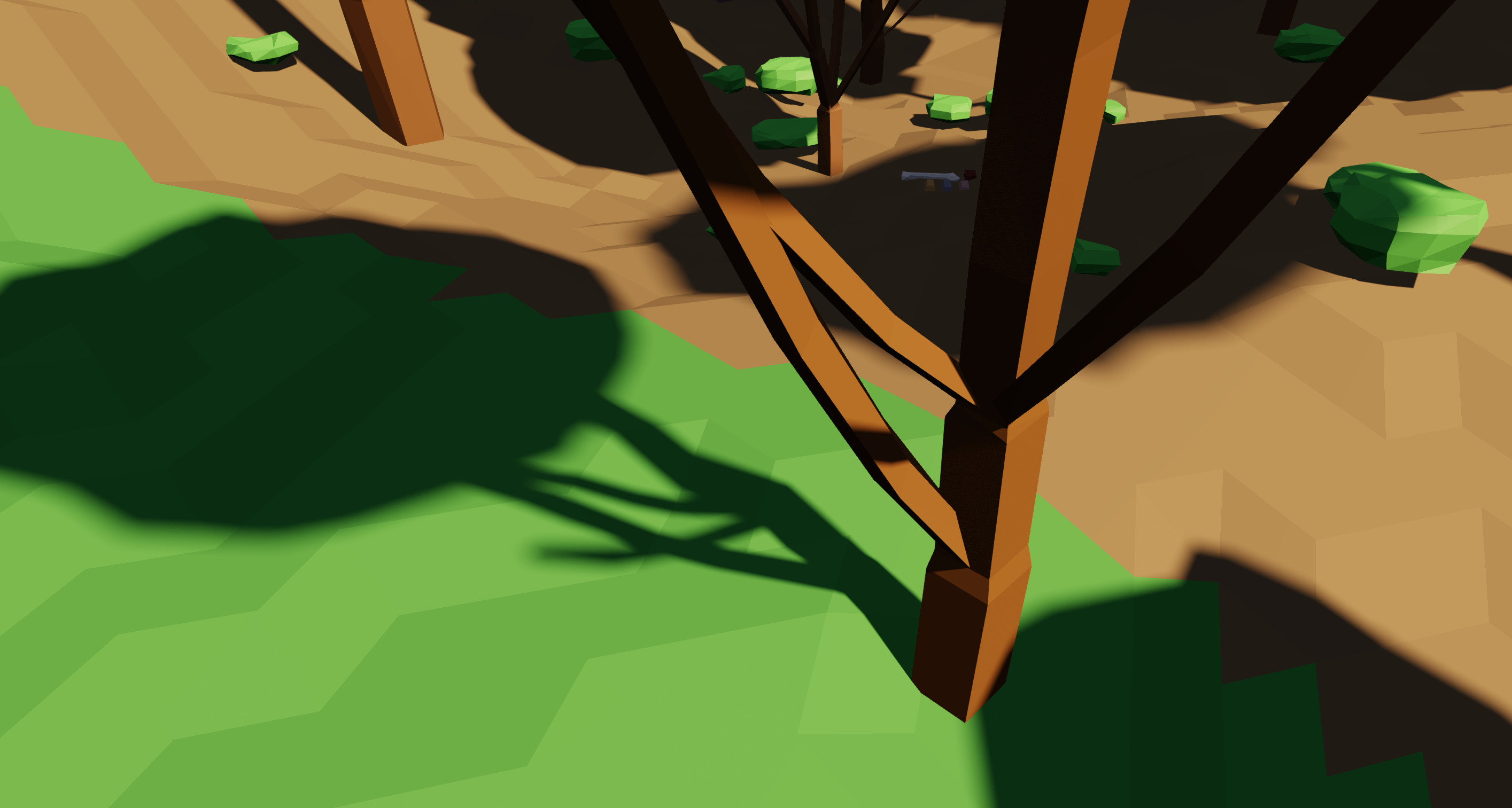 Variable penumbra achieved by the presented technique
Main idea
Our goal is to determine how much a particular fragment is shadowed. For now, let’s focus on the sun: a sphere light source with parallel light rays in our scene. Imagine sitting at the fragment and looking at the sun (with protective glasses, of course!). You would see a disk, which we will assume has the same brightness at every point.
 Left: unoccluded sun. Right: Sun partially occluded by scene geometry.
Naturally, scene geometry could partially or fully block the circle, stopping some light from reaching the fragment. We need to determine what fraction of that light source disk is blocked by scene geometry. That directly gives us the shadow amount for that fragment.
- For each fragment:
total_sun_occlusion := not occluded- For each shadow-casting triangle:
- Project onto that fragment’s view of the sun disk
- Determine occlusion and add to
total_sun_occlusion
- Return
total_sun_occlusionas shadow amount
Of course, doing this naively and looping through all scene triangles for each fragment would be extremely slow. To speed this up, I quickly cull large number of triangles in various stages so that each fragment only has to consider a small number of triangles. The culling step is explained in this chapter below.
Fragment occlusion
Projection onto sun disk
Let’s define the sun disk space such that the sun’s center is at (0, 0) and has a radius of 1.
We need to project all three vertices of a triangle into that space.
Our inputs are:
- World space position of the three vertices (
v0,v1,v2) - World space position of the fragment (
fragment_pos) - Constants (at least for a given frame):
- Light direction
- Angular radius of the sun
First we transform all world space positions into “light space” where +z points towards the sun. The x and y axes are two arbitrary axes perpendicular to z and each other. To transform from world space to light space, a transformation matrix can be constructed on the CPU beforehand. Then, transforming from world to sun disk space looks like this:
let tmp = (to_light_space_matrix * v0) - (to_light_space_matrix * fragment_pos);
let v0_in_disk_space = tmp.xy / (sin(angular_radius) * tmp.z);
The second line performs the perspective divide and uses the angular radius as field of view.
Usually, there is actually quite a bit of hidden complexity here: a triangle is not necessarily a triangle after perspective divide.
If some, but not all vertices of the triangle are behind the camera (i.e. the sign of tmp.z in this case), then it gets quite complicated.
Hardware rasterizer typically deal with this by clipping the triangle before perspective divide, but there are alternative approaches called “clip-less rasterization”.
For more information see this post, this post, or this patent.
I dealt with the problem by flipping the line equations depending on the sign of z value.
This is similar to the techniques described in the links above.
See the xor_mask calculation in the shader code linked below.
Determine occlusion via rasterization
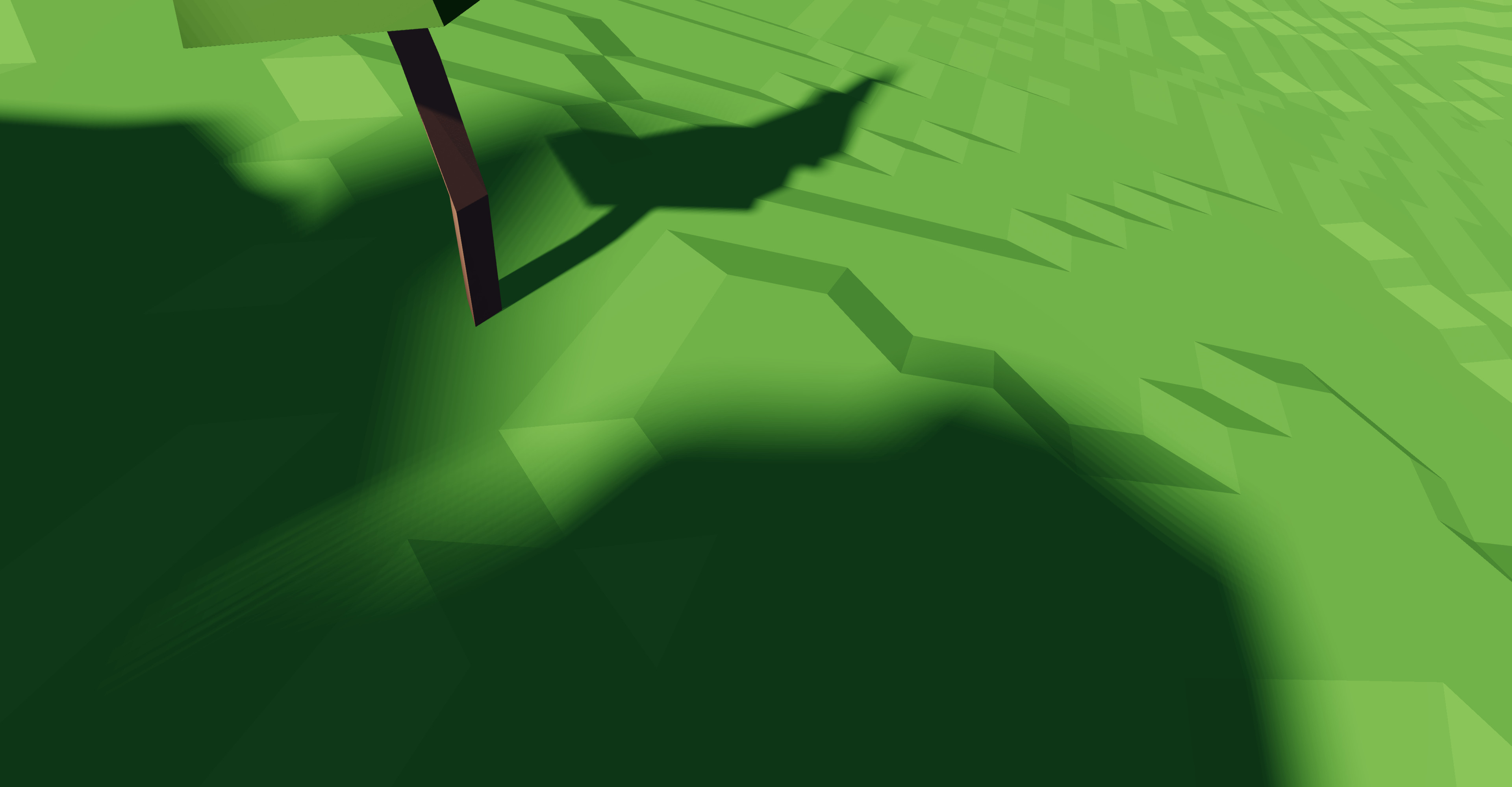
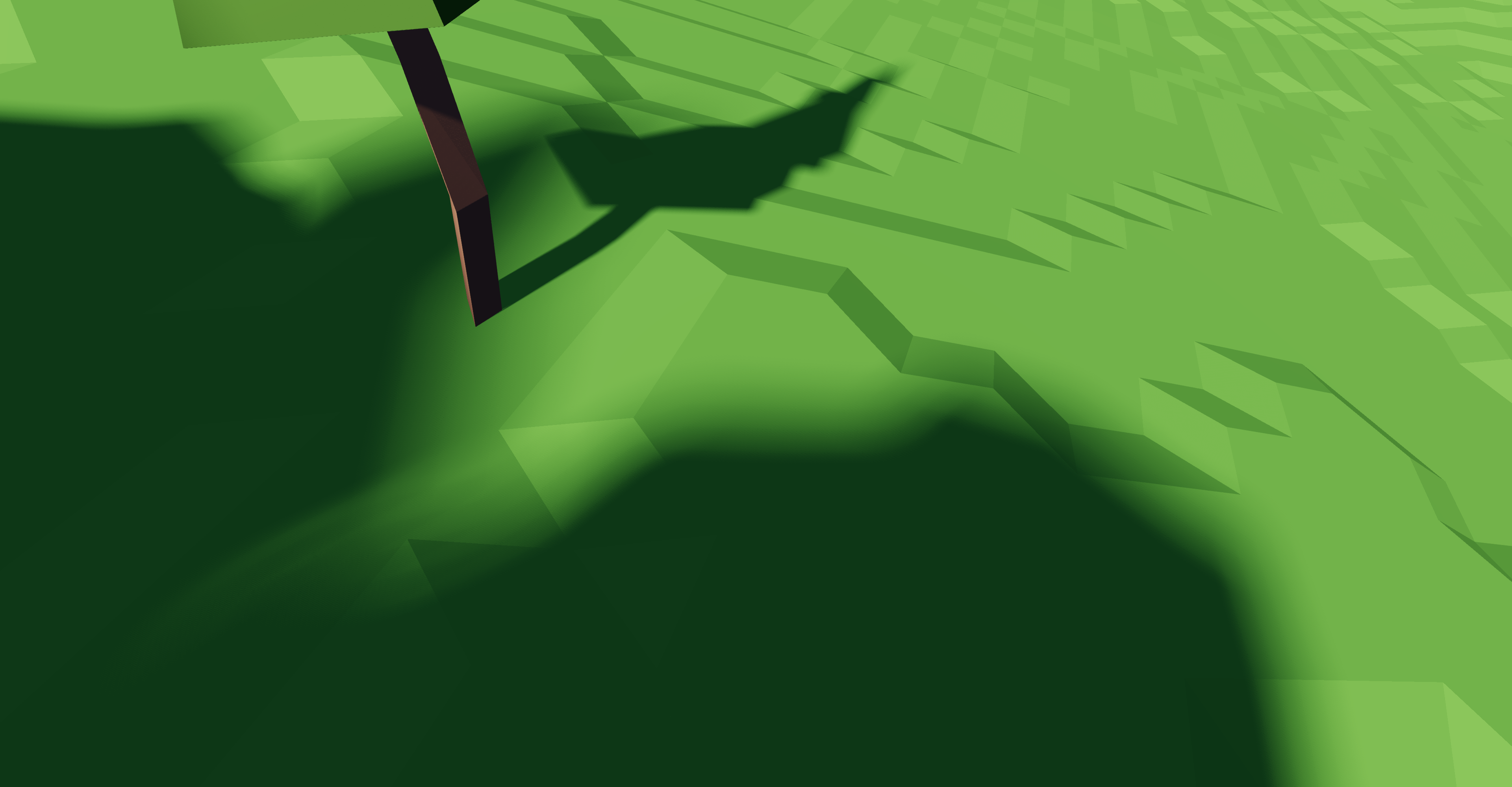
First, I tried to analytically determine the exact overlap area of disk and the projected triangle and then add up all those overlap areas. However, that is incorrect: two triangles could both block the left half of the sun. The fragment would be 50% shadowed, but summing up both overlap areas (0.5 + 0.5) would result in a shadow amount of 1. The artifacts caused by this can be seen in this video (notice how the human shadow on the left grows outwards when the tree shadow gets closer):
Instead, all projected triangles are rasterized to a 16×16 grid represented as array<u32, 8> (i.e. a bitset).
A set bit indicates light, a cleared bit indicates that this pixel is outside of the disk or is blocked by geometry.
Since we are only interested in the disk, some pixels in this grid are wasted.

The basic setup looks like this:
// Intialize the disk inside our grid to 1, everything else to 0.
var grid = array<u32, 8>(
    0x07e01ff8u, 0x3ffc7ffeu, 0x7ffeffffu, 0xffffffffu,
    0xffffffffu, 0xffff7ffeu, 0x7ffe3ffcu, 0x1ff807e0u,
);

for (/* all  pre-culled shadow-casting triangles */) {
    // Rasterize to grid, clearing some bits...
}

// Count set bits, divide by number of pixels inside disk. This `occlusion` is
// the final shadow amount for this fragment.
let occlusion = 1.0 - f32(countOneBits(grid)) / 208.0;
For each triangle in the loop, I first perform a few simple checks to quickly reject irrelevant triangles. The rasterization consists of the following steps:
- Determine line equation for each triangle edge.
- For each scanline in grid:
- For each triangle edge:
- Evaluate edge equation to get the x coordinate (from 0 to 1) of the edge-scanline intersection.
- Multiply x coordinate by 16 and shift
0xFFFFright by that amount. That gives us a bit mask with 1s right of the edge, and 0s left of the edge. - Conditionally flip that mask such that the 0s are on the “inside triangle” side of the edge.
- Bitwise or all edges’ bit masks, resulting in a mask with bits cleared only inside the triangle.
- Bitwise and the resulting value with the existing line of the grid.
- For each triangle edge:
You can see code with some comments here. By using bit-fiddling tricks, the work per scanline is constant, making the whole operation okayish fast. Very roughly, on an RTX 4070, rasterizing an average of 30 triangles per pixel at 4k, takes 5ms.
Fixing banding
Unfortunately, the rather small grid size of 16×16 causes banding artifacts when a triangle edge is aligned with the grid axis:
Fortunately, this problem is well known in the world of real-time shadow and it is typically dealt with by introducing some kind of randomness to trade banding for noise. Randomly rotating the grid resolves the issue without introducing any visible noise (at least to my eyes):

If you pixel-peep, you can see the noise and the fact that I’m currently not using a good noise function. Some small amount of banding is still visible, but both artifacts are hardly noticeable in my opinion.
Grid size optimization
As the cost per scanline is constant up to the word-width 32, one can easily up the resolution in that dimension, “only” paying memory costs. Using all 32 bits is not easily possible as shifting right by 32 is not well defined and usually does not what we want (completely clearing the word). With only 31, the shift trick works without problems. As we only have one line per array element, the inner loop can also be simplified.
The number of lines can be adjusted fairly freely and can thus be used as “shadow quality” setting. You can compare the visible banding artifacts here: 3 lines (2.1ms), 5 lines (2.5ms), 7 lines (3.1ms). The given durations are for only the rasterization step for a specific scene, and are very rough estimates. For comparison, the 16×16 grid explained above took 5ms.
Texturing/alpha masking?
As with most per-triangle shadow volume techniques, using textures to make part of the geometry transparent is possible, at least in theory. In practice, this would likely make the actual rasterization a lot slower. Currently, each scanline merely needs a few adds, multiplications and bit-operations. To use texturing, the texture coordinate needs to be interpolated and for each pixel that is not yet occluded, a texture fetch needs to happen.
So while I have not tried this yet, I don’t have high hopes regarding performance. I’d love to be proven wrong, of course.
Culling
To make all of this even remotely possible, the number of triangles each fragment has to rasterize needs to be fairly low. I achieved this in multiple culling steps.
- I assume the scene is already pre-partitioned into mesh clusters for GPU-driven rendering and that each mesh cluster stores a bounding sphere. This forms a two-level hierarchy, meaning we can first cull clusters, and then consider individual triangles of surviving clusters only.
- I also use tile-based culling, very similar to tile-based deferred rendering. Each 16×16 fragment “tile” of the render target shares culling work.
I use truncated infinite cones as bounding volumes for the space that could be shadowed by an individual triangle or a mesh cluster.
The angle of the cone is the angular radius of the light source (still only talking about directional lights).
It is truncated as the triangle cannot shadow anything that is closer to the cone’s tip than the closest vertex of said triangle.
Since the angular radius and light direction are constant (per frame), the cone can be stored as tip: vec3f and start_height: f32.
 The truncated cone for the shown blue triangle.
Two main passes, both compute, are involved:
Gather pass
In this step, the whole scene is culled against the camera frustum (clusters first, then triangles). Unfortunately, this is less effective than normal culling as geometry outside the frustum can shadow stuff inside the frustum. If view and light direction are too aligned, nothing can be culled like that.
Further, triangles facing the light are culled. Back face culling works too, but front-face culling usually removes more triangles as terrain usually points towards the light.
The surviving triangles, clusters and their cones are densely packed into output buffers.
Eval pass
One workgroup (of size 256) per 16×16 pixel tile in the render target is launched. For each pixel, the normal is looked up in the G-buffer and pixels not facing the light are marked as irrelevant (they are not lit anyway). Further, sky pixels (with far plane depth value) are marked irrelevant as well. Tiles with no relevant pixels early exit here.
Next, the minimum and maximum depth value of all relevant pixels in that tile is determined. From that, a bounding volume containing the 3D positions of all relevant pixels in this tile can be computed. Depending on the depth range, I either use a sphere or a capsule where one side has a different radius than the other.
The output of the gather step is then culled against said bounding volume. This is performed in two steps, again: first culling mesh clusters, then individual triangles. Each thread of the workgroup deals with a different cluster/triangle, parallelizing the culling. In both steps, the surviving clusters/triangles are stored in a workgroup-shared-memory buffer. So at the end, each workgroup (i.e. each 16×16 tile) has a list of triangles potentially shadowing pixels within that tile.
Finally, the rasterization step described in the previous chapter is performed, with the triangle list as input.
Depth discontinuities & half-z
A well known problem with this tiled approach is depth-discontinuities, which lead to bad culling, i.e. many surviving triangles that do not shadow any relevant pixel. As the shared-memory buffer has a fairly limited size, I can only store a few thousand triangles. This limit is quickly reached for tiles with large depth ranges, especially during sunset or sunrise. In those cases, I draw a checkerboard pattern for debugging, in case you already spotted that in the images/videos.
I implemented the half-z approach where the initial depth range is split into half and the exact bounds of the two halves are recalculated. The results weren’t as good as expected though. An approach similar to clustered deferred rendering could be used, which splits the depth range into many ranges, completely side stepping the depth-discontinuity issue. I have not tried this yet.
Discussion and other notes
I’m fairly certain my culling is far from perfect. There are a number of papers introducing more sophisticated data structures to quickly perform that culling. For example: Per-Triangle Shadow Volumes Using a View-Sample Cluster Hierarchy by Sintorn, E., Kämpe, V., Olsson, O., & Assarsson, U. (2014, March).
The only real advantage of my approach is that it’s relatively easy to implement and is based on two widely used techniques (GPU-driven rendering & tiled rendering).
I’m very interested in revisiting this topic and explore completely different approaches too. For example, I would like to try building a data structure holding all shadow cones, allowing quick lookup of all cones including a given point. Something something “reduce to 2D”, “interval trees”, …
As a final note, the cone-frustum intersection test required for this culling is… tricky. Also, finding the optimal bounding cone for a triangle, reducing to the PCC variant of Apollonius’ problem, is non-trivial. This made me realize that my math/geometry skills are not up to the task 🙁 So I often used sub-optimal approximations.
Performance
On my RTX 4070, I got around 60fps at 4k for a scene with ≈13M triangles (in ≈30K clusters). The gather step (which takes ≈1.3ms) reduces that to ≈2.5M triangles (in ≈18K clusters). The eval step takes most of the remaining frame time.
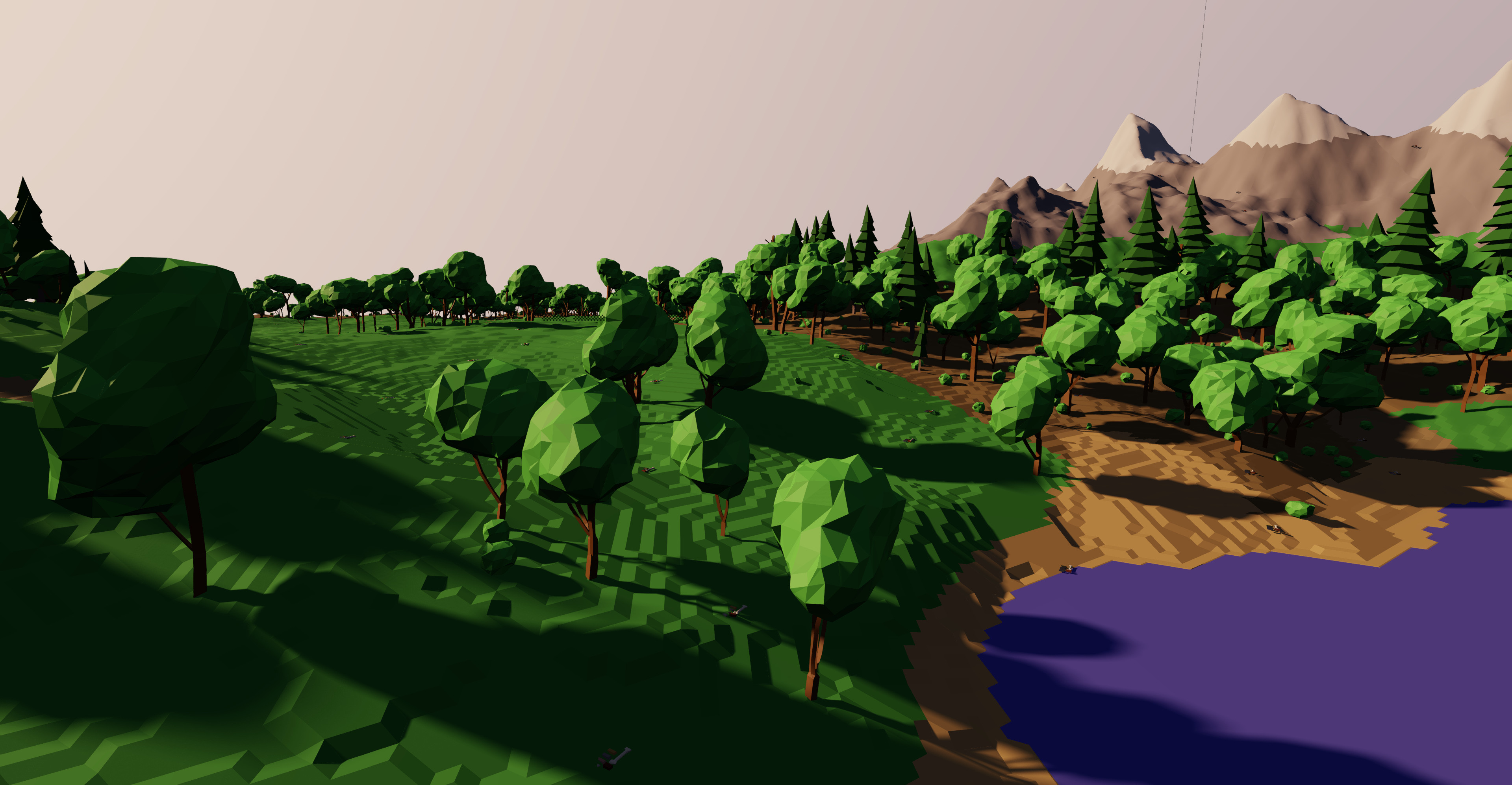
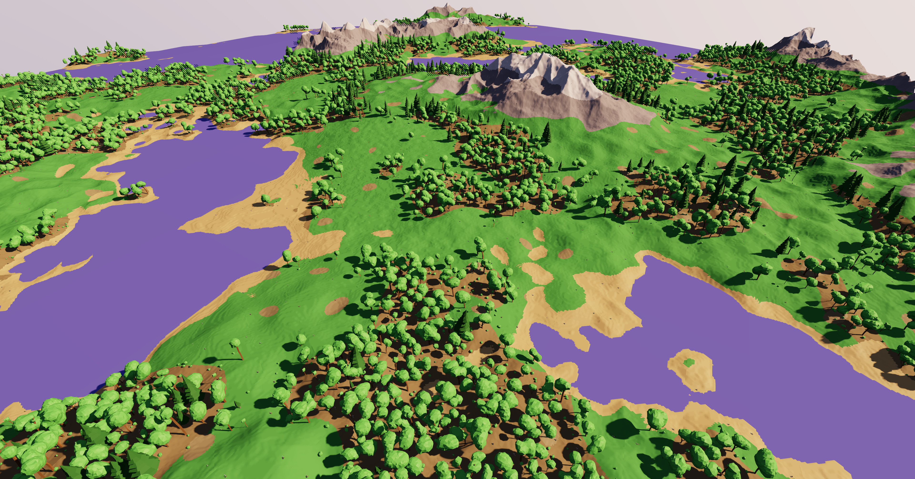 Example scene with the numbers above.
All of this depends a lot on the view and the sun elevation, though. Sunsets and sunrises are very demanding and many tiles run into their triangle limit. Further, if a shadow from a distant objects covers a large part of the screen, the rasterization routine has to run very often, also resulting in a big FPS drop.
Two important notes: First, my mesh clusters currently have widely varying sizes which is very bad to fully utilize all of the GPU. Second, I have no LOD system yet at all, meaning that all objects in the above screenshot are not only rendered at full mesh-resolution, but the the highest-resolution mesh is also used for shadow calculations. Addressing these shortcomings might yield quite a good performance improvement in real world usage.
I obviously skipped lots of details in this article, but I hope my explanation was sufficient anyway. Feel free to reach out if you have any questions or want to discuss this.
In the future, I will try to get this to a shippable state. There is still lots to explore and optimize about this. But for now I will focus on other parts of my app, transitioning it from “tech-demo” to “game”.